Pipelining
Note: modern CPU do not work this way.
MIPS Overview
Developed by MIPS Technologies in 1984, first product in 1986. Used in:
- Silicon Graphics (SGI) Unix workstation
- Digital Equipment Coporation (DEC) Unix workstation
- Nintendo 64
- Sony PlayStation
Also the inspiration for ARM (esp v8)
It is a 32 bit archnitecture (registers, memory addresses) and has 32 registers. Has multiply and divide instructions and floating point numbers.
Operations
To perform addition: , the MIPS instruction would be add a,b,c where a, b, c are registers.
32 Registers
The following registers are special:
- 0 (number)
$zero(name) always has the value 0 - 31
$racontains the return address
Other conventions guide that:
- 1
$atreserved for pseudo-instructions - 2-3
$v0-$v1return values of a function call - 4-7
$a0-$a3arguments for a function call - 8-15,24,25
$t0-$t9temporaries, can be overwritten by function (callee saved) - 16-23
$s0-$s7saved, have to be preserved by function (caller saved) - 26-27
$k0-$k1reserved for kernel - 28
$gpglobal area pointer stack pointer frame pointer - 29
$spstack pointer - 30
$fpframe pointer
Pipelining
An approach to efficiently perform work when your unit of work is a subtask, and each subtask requires a certain resource.
Laundry Analogy
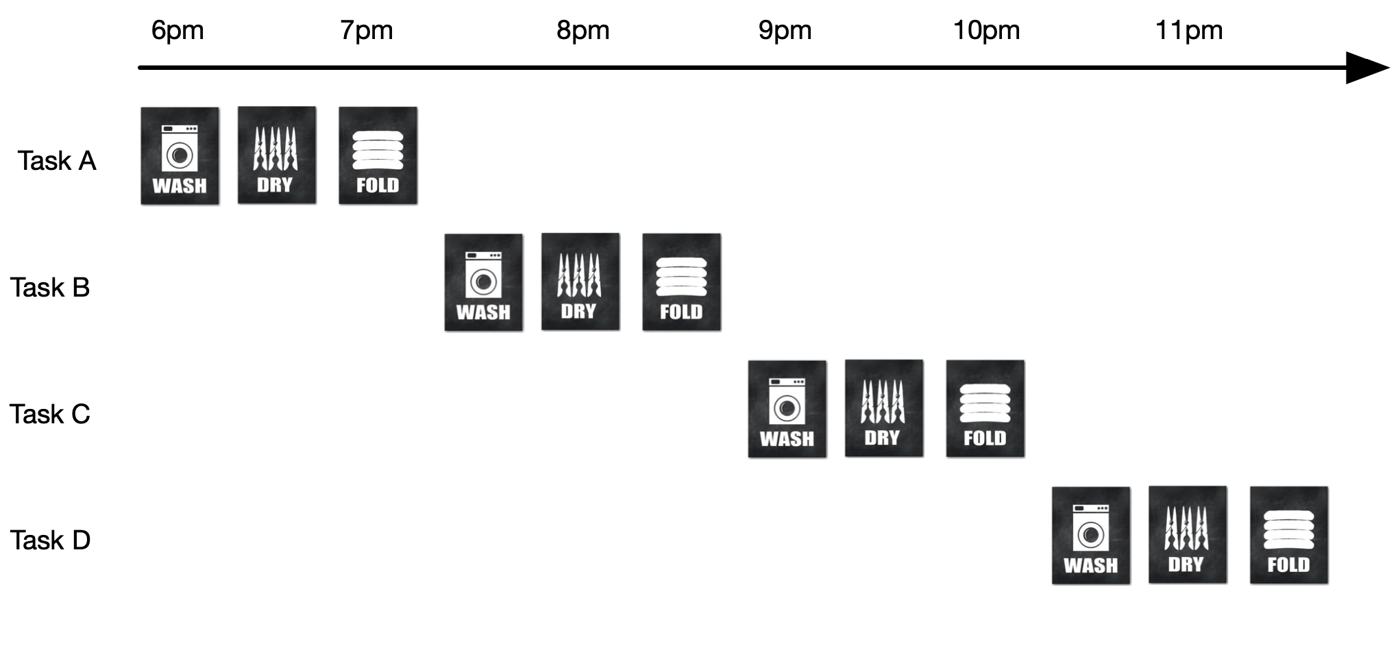
Sequential:
Pipelined:
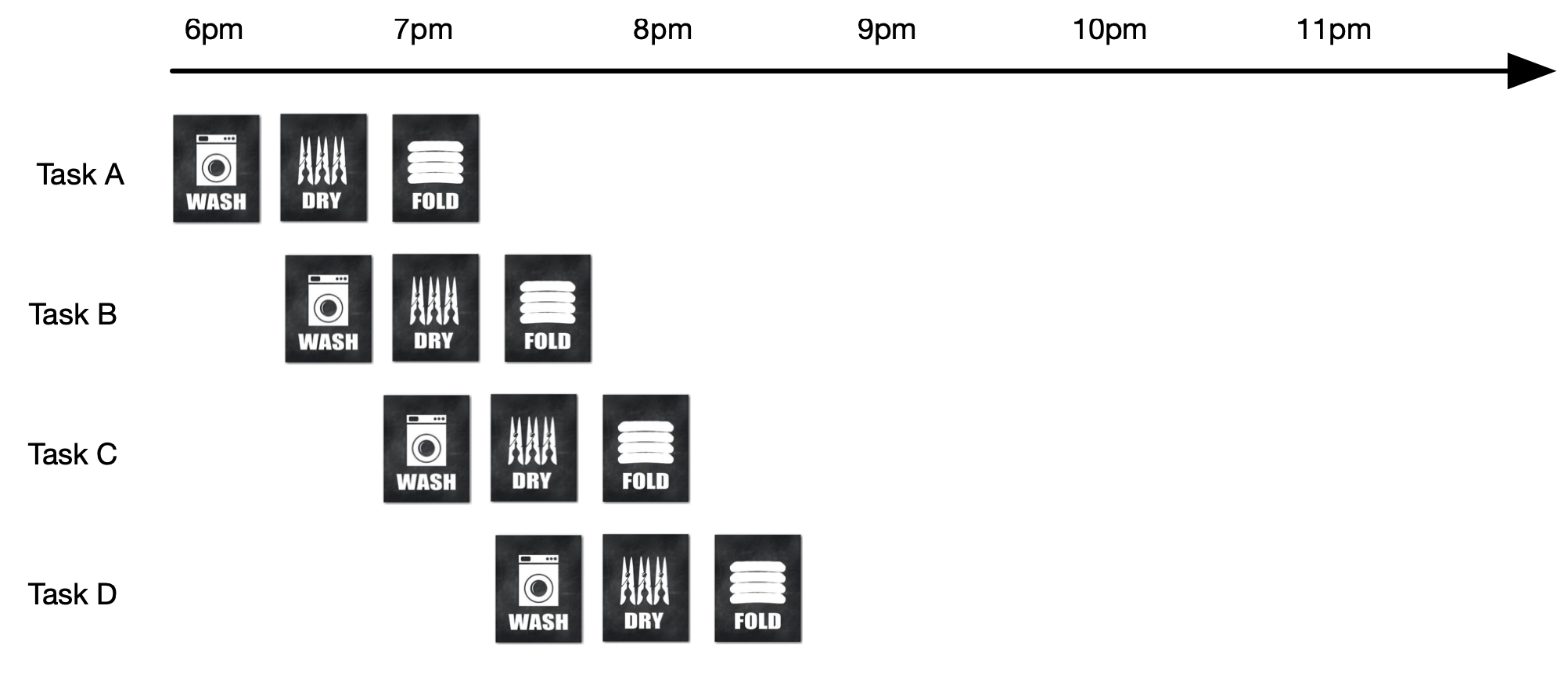
- Theoretical speed up of 3 times.
- Actual speed up time is 2 times.
- sequential: 1:30+1:30+1:30+1:30 = 6 hours
- pipelined: 1:30+0:30+0:30+0:30 = 3 hours
Many tasks → speed-up approaches theoretical limit
MIPS Instruction Pipeline
5 Stage Pipeline:
- Fetch instruction from memory
- Read registers (get data value) and decode instruction to provide guideline to later stages
- note: registers are always encoded in the same place in instruction
- Execute operation or calculate an address (Compute stage).
- Access (loads or store) an operand in memory
- Write result into a register
Timing
For each type of instruction, there is a different time.
| Instruction Class | Instruction Fetch | Register Read | ALU Oper. | Data Access | Register Write | Total Time |
|---|---|---|---|---|---|---|
| Load word (lw) | 200ps | 100ps | 200ps | 200ps | 100ps | 800ps |
| Store word (sw) | 200ps | 100ps | 200ps | 200ps | 700ps | |
| R-Format (add) | 200ps | 100ps | 200ps | 100ps | 600ps | |
| Brand (beq) | 200ps | 100ps | 200ps | 500ps |
- The fetch time is the time it takes for one cycle.
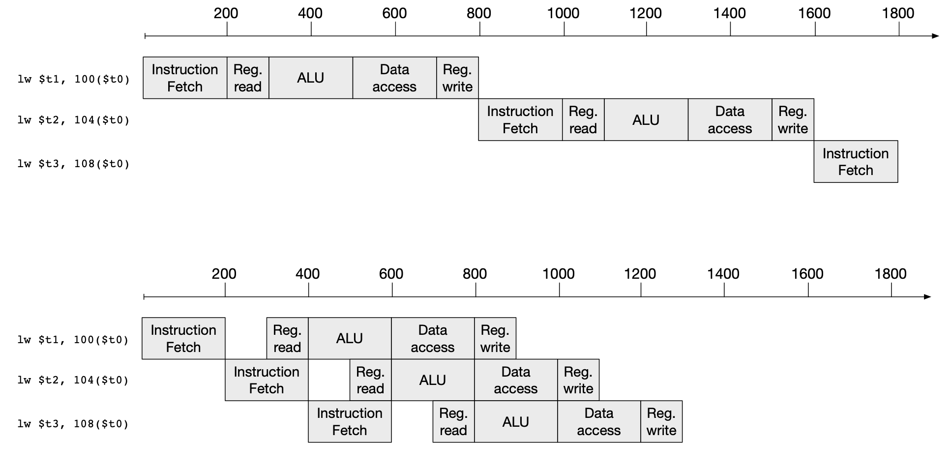
- Theoretical speed-up: 4 times
- Actual speed-up in example: 1.71 times
- sequential: 800ps + 800ps + 800ps = 2400ps
- pipelined: 1000ps + 200ps + 200ps = 1400ps
- Many tasks → speed-up approaches theoretical limit
Design for Pipeline
In MIPS, pipelining is much simpler than x86:
- All instructions are 4 bytes → its easy to fetch next instruction
- Few instruction formats → parallel op decode and register read
- Memory access limited to load and store instructions → stage 3 used for memory access, otherwise operation execution.
- Words aligned in memory → able to read in one instruction
- Aligned = memory address multiple of 4
Hazards
- Hazard = next instruction cannot be executed in next clock cycle
- Types
- structural hazard
- data hazard
- control hazard
Structural Hazard
Instructions overlap in resource use in the same stage For instance, memory access conflict.
| 1 | 2 | 3 | 4 | 5 | 6 | 7 | |
|---|---|---|---|---|---|---|---|
| i1 | FETCH | DECODE | MEMORY | MEMORY | ALU | REGISTER | |
| I2 | FETCH | DECODE | MEMORY | MEMORY | ALU | REGISTER | |
| conflict!! |
MIPS doesnt have structural hazards because there is always 5 stages.
Data Hazard
Instruction waits on result from prior instruction; data dependencies For instance,
add $s0, $t0, $t1
sub $t0, $s0, $t3
subreads$s0on stage 2, which depends onaddwriting to$s0in stage 5.- Therefore, stage 2 of
submust be delayed.
We overcome this in hardware.
Units:
IF: instruction fetchID: instruction decodeEX: executionMEM: memory accessWB: write-back
For Add and Subtract:
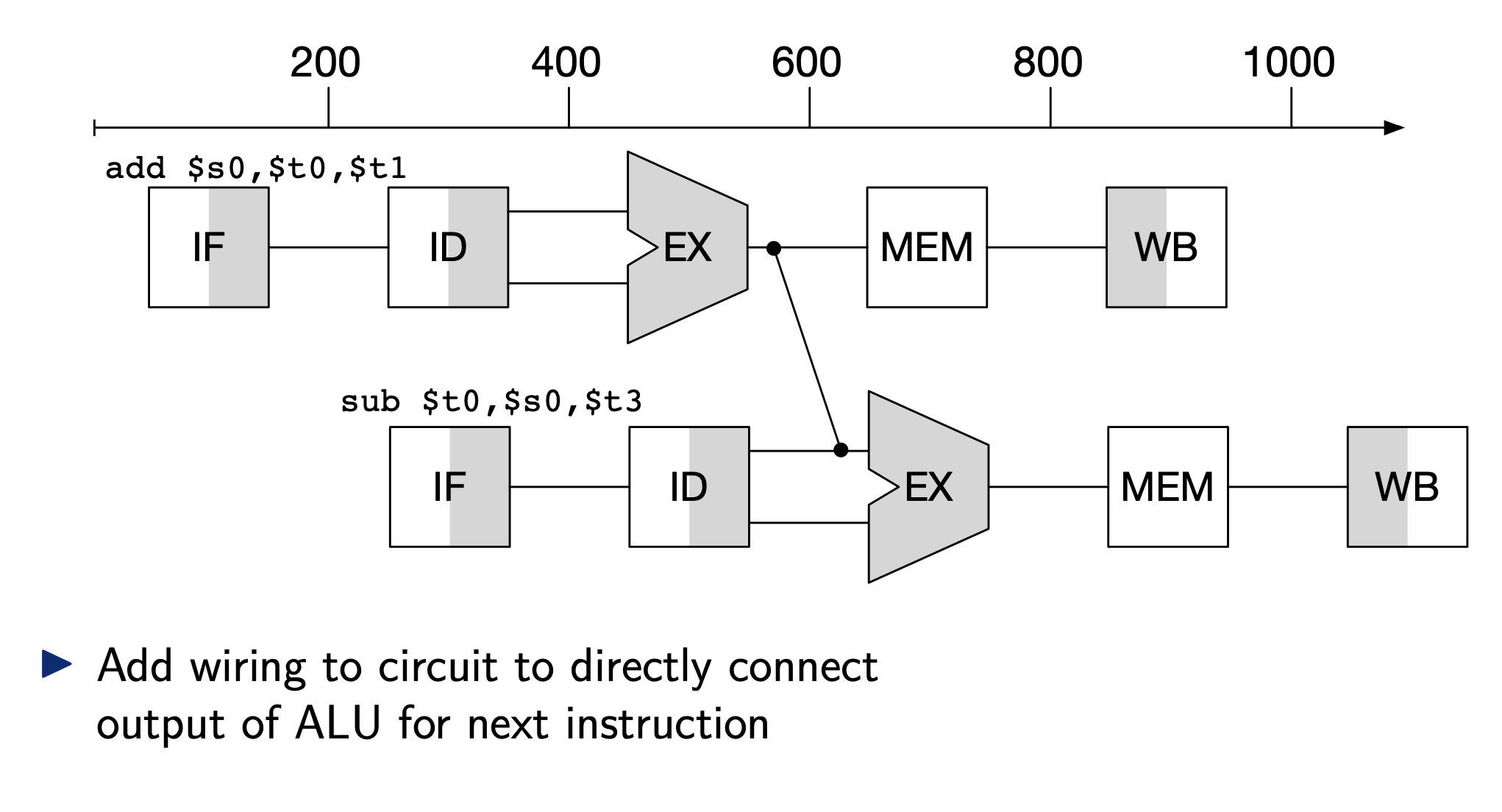
We add wiring to circuit to directly connect output of ALU for next instructions.
For Load and Subtract, we must wait for the data to be loaded into memory first.
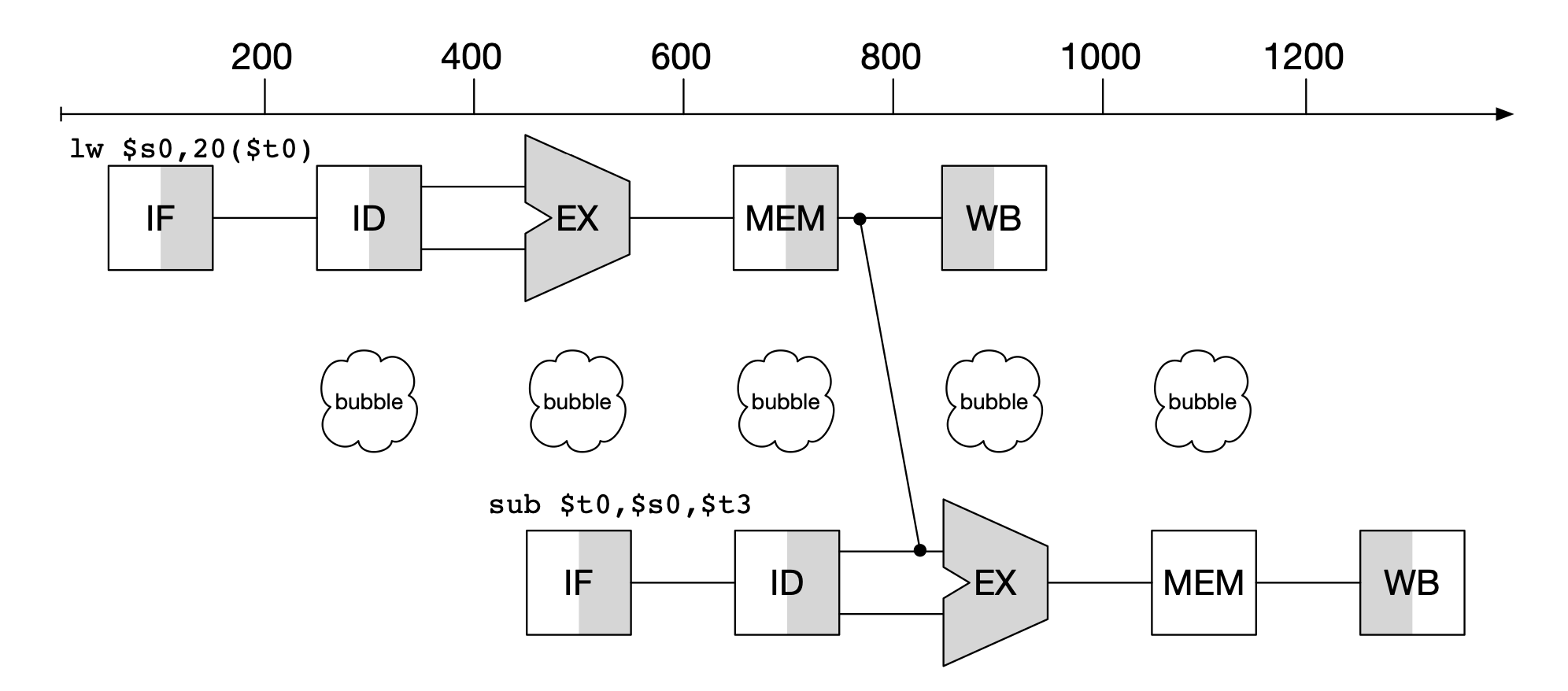
- Add wiring from memory lookup to ALU
- Still 1 cycle unused: "pipeline stall" or "bubble"
Solution The compiler will reorder the code so that dependent instructions are not too close to one another. That way we fill the delay by adding another instruction.
Control Hazard
Also called branch hazard.
Selection of next instruction depends on the outcome of previous.
Example
add $s0, $t0, $t1
beq $s0, $s1, ff40
sub $t0, $s0, $t3
- sub instruction only executed if branch condition fails → cannot start until branch condition result known
Brand Prediction
-
Assume that branches are never taken → full speed if correct
-
More sophisticated
-
keep record of branch taken or not I make prediction based on history
Linked from Computer System Fundamentals