IP
IP Packet
Recall that the IP Packet consists of a header and the payload.
- the payload is opaque to the network. the network cannot interpret the payload.
- header is what we care about.
- first end-to-end layer.
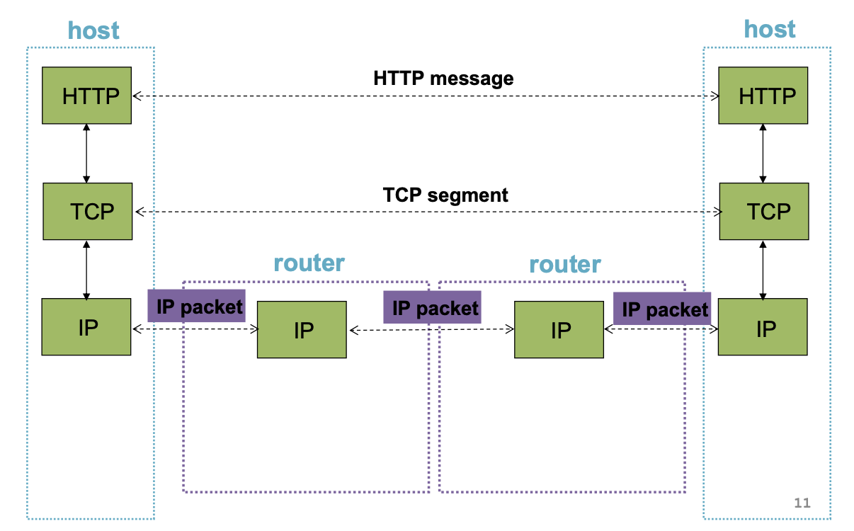
Analogy: HTTP with the application layer, TCP with the transport layer, and the IP with the network layer.
Header
The IP Header is an interface. It's the interface between the source and destination end-systems and between the source and network (routers).
It's structure looks like the following:
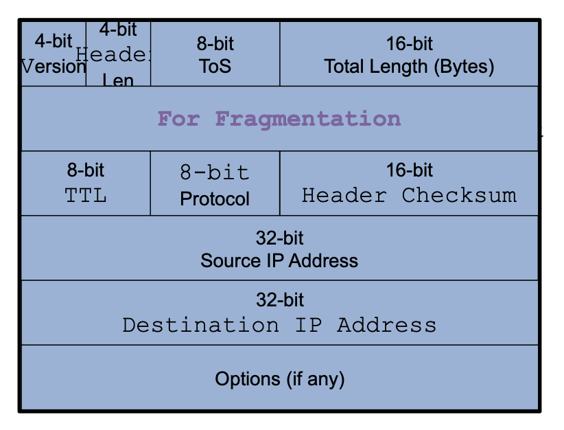
Goals of the IP Header The header reflects information needed for basic tasks. The tasks goals in the network are (and the sub bullet describes what part of the packet is used to accomplish it):
- parse the packet
- Use the IP version number (4 bits) and the packet length (16 bits)
- carry the packet to the destination
- Use the destination's IP address (32 bits in IPv4 or 128 bits in IPv6)
- be able to deal with problems along the way like loops, corruption, too large of a packet
- loops can be addressed with the TTL (time to live, 8 bits) so that the router can increment the TTL by one before it starts parsing it.
- corruption is addressed with the checksum (16 bits). It's re-calculated each time before it enters the router. It must be re-calculated because we update the header by incrementing the TTL at each router.
- too large of the packet is the responsibility of the identification, fragment offset, and flags.
- accommodate evolution
- version number (4 bits) + fields for special handling.
- specify any special handling.
- ToS (types of services, 8 bits), options (variable length)
Options is part of the header and it contains the optional directives to the network.
- not frequently used.
- 16 bits of meta data + option-specific data
- Some examples include: record route (what is the route that the packet has traveled in the network), strict source route (at the source, delegate what the full route you want the packet to take), loose source route (specify the route, but only a part of it), timestamp (understand if you are locked in a overloaded queue, or is the link rate too high).
Forwarding loops cause packets to cycle for a long time. Avoid loop because if left unchecked, it would consume all capacity.
Fragmentation is when a router splits a packet into multiple "fragments" if the packet size exceeds the link's MTU. If we split, we must be able to reassemble to recover the original packet.
- every link has a "maximum transmission unit" (MTU). The largest number of bits it can carry as one unit.
Special handling: the "type of service" (8 bits)
- allows packets to be treated differently based on needs. E.g., indicate priority, congestion notification.
- this has been redefined several times
- now called DSCP, "Differentiated Service Code Point"
It helps achieve the tasks and goals at the destination end-system:
- tell destination what to do with the received packet
- Transport layer protocol (8 bits)
- get responses to the packet back to the source.
- Source IP address (32 bits)
So how do we tell the end-host how we want to handle the packet?
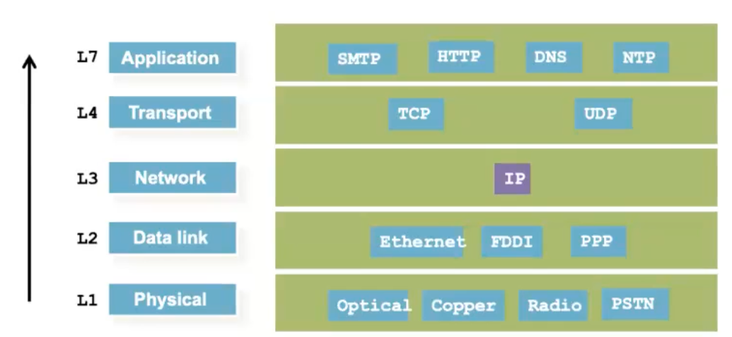 Process it from bottom to top. The IP layer will take out the IP header, but where is it passed off to? This process is called de-multiplexing. This is where the protocol (8 bits) field comes into play. It tells the end-host how to handle the packet.
- it identifies the higher-level protocol. For example, "6" would mean to pass it off to the TCP or "17" for UDP
- important for de-multiplexing at the receiving host.
Fragmentation
Fragmentation is the process where if the packet size exceeds the MTU value (too large to process), then the router will split it. We must be able to reassemble it. Fragmentation is performed it the router.
Example:
- a 4000 byte packet crosses a link w/ MTU = 1500B
- the IP headers (ignoring the options) is 20 bytes. The rest of the data (3080) is the packet we are trying to send.
- The first fragment will be 20 byte header + 1480 byte data.
- Second and third fragment will be 20+1200 (total 1220) and 20+1300 (1320) bytes.
- For each of the fragment, you must add the IP header.
- The fragment must be reassembled before it is handed off to the higher layers
- This is because the TCP/UDP headers will be in the beginning, which will be needed by the other packets.
Few things to consider:
- where do we reassemble the fragment?
- what if the fragments get lost.
- what if the fragments follow different routes?
- what if the fragments get fragmented again?
Reassembly
Thinking about to do reassembly is a classic case of E2E principle, the idea that certain functions and features should be implemented at the endpoints (or edges) of a network rather than in the network core. The basic idea is to keep the core of the network simple and robust, while more complex functions are delegated to the ends of the network.
We don't want to reassemble in the network for two reasons:
- At next-hop router imposes burden on network
- complicated reassembly algorithm because you must keep state of each of the fragment
- you have to buffer them somewhere so you can capture all the fragments so it'll be a burden on the network
- Any other router may not work because fragments may take different paths.
- In general, there is little benefit, and there is a large cost for performing network reassembly. This is why reassembly is done at destination
Implementation
Necessary fields for reassembly:
- we need an identifier which identifies fragments as parts of one packet.
- fragments can get lost, so we need some sequence number or offset.
- An offset/sequence will show the position of the fragment in the list of all the fragments.
- We need a max sequence or a flag so that you know whether you have them all?
- Consider: What if a fragment gets re-fragmented? (it's okay because we are using offset)
The IPv4 Fragmentation Fields:
- identifier: which fragments belong together (16-bits)
- flags: (3 bits)
- (R) reserved: ignore
- (D) DF: don't fragment (may trigger error back to sender)
- (M) MF: more fragments coming
- offset: portion of original payload this fragment contains (in 8-byte units) (13 bits)
These fields work because
- fragment without MF indicates its the last fragment. This tells the host which are the last bits in the original payload
- all the other fragments fill in the hole. Tell when holes are filled, regardless of order by using the offset field.
- Why use a byte-offset for fragments rather than numbering each fragment?
- if we face another fragmentation, then we know that its going through another fragmentation.
Example
Example of fragmentation:
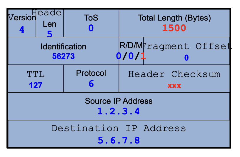
- split 4000 byte packet (20 header, 3980 payload) into 3 packets. The original packet has identification 54273, total length 4000, R/D/M 0/0/0, fragmentation offset 0, header checksum 44019:
- 20 header, 1480 payload. identification 54273 (same), total length 1500 (length has changed), R/D/M 0/0/1 (more coming), fragmentation offset 0 (first fragment we are sending), header checksum xxx (needs to be recalculated because the fields in the IP header has changed).
- 20 header, 1200 payload. identification 54273 (same), total length 1220 (length has changed), R/D/M 0/0/1, fragmentation offset 185 (second fragment we are sending, note that we don't include the frag ipv4 header), header checksum xxx (needs to be recalculated because the fields in the IP header has changed).
- 20 header, 1300 payload. identification 54273 (same), total length 1320 (length has changed), R/D/M 0/0/0, fragmentation offset (note that M is now 0 because this is the last packet), 335 (third fragment we are sending, note that we don't include the frag ipv4 header), header checksum yyy (needs to be recalculated because the fields in the IP header has changed).
Network Switching
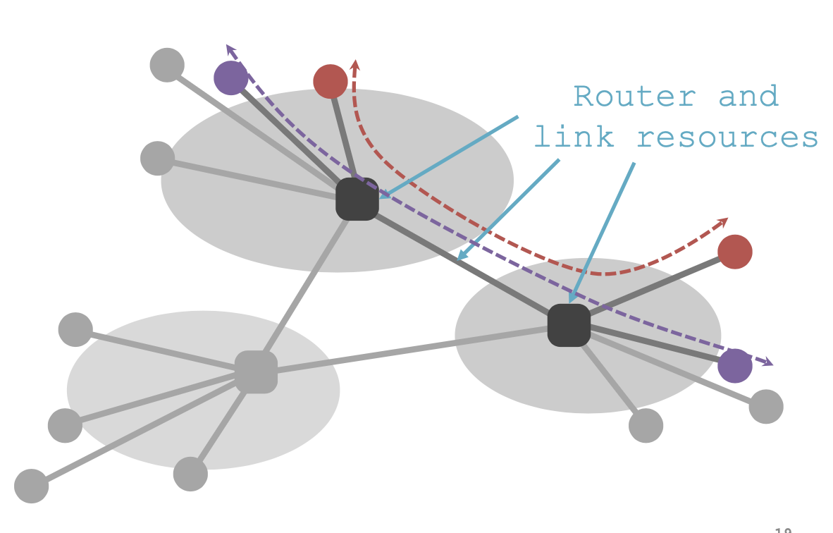 We needed to come up with a solution to share resources in the network. Networking switching are fundamental networking paradigms that describe how data is transferred between devices in a network.
The two ways to share switched networks:
- circuit switching:
- resources reserved per connection
- admission control
- packet switching via statistical multiplexing
- Packets treated independently, on-demand
- Admission control: per packet
- Hybrid: virtual circuits
- Emulating circuit switching with packets (see text)
Circuit Switching
Circuit switching uses a established, dedicated, and continuous physical communication path, or circuit, between two devices.
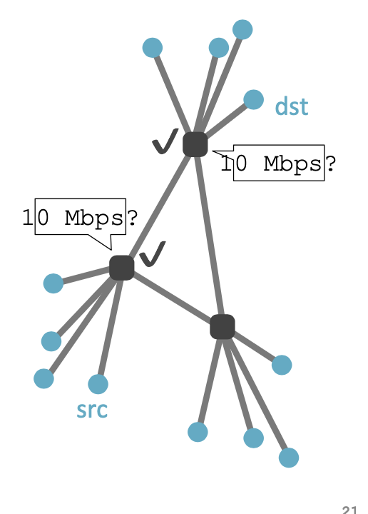 We have two different domains, and we want to share between them.
- src sends reservation request to dst
- routers create circuit after admission control
- src sends data
- src sends teardown request (and release the resources)
It's called circuit switching because reserving establishes a "circuit" within a router
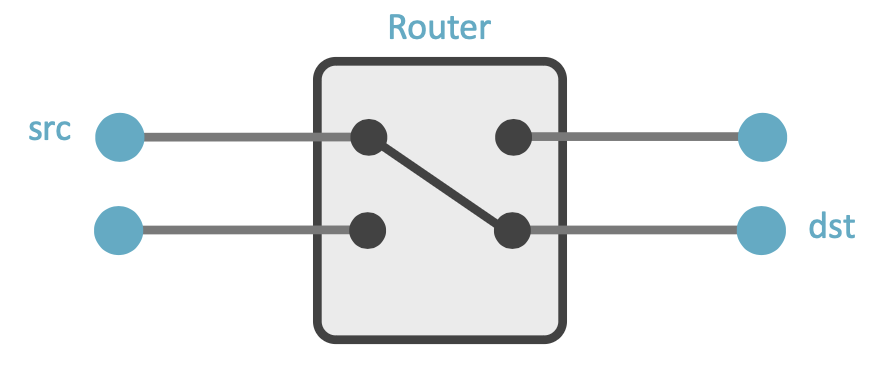
- there is a link between the input source and the output source. The direct link has the capabilities that the src requested.
Pros:
- predictable performance
- simple and fast switching once the circuit established
- reliable, in-order delivery
- simple forwarding
- no overhead for packet headers
Cons:
- complexity as you setup and teardown the circuit connection
- inefficient when the traffic is bursty
- circuit setup adds delay
- if the connection breaks in the middle of transit. we'll loose all that data
Circuits can be of many types.
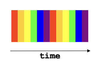
- Time division multiplexing divides time in time slots, and there is a separate time slot per circuit. There is a static amount of resources established between the src and dst. You have to wait until your time slot before you can send data.
- Frequency division multiplexing: divide frequency spectrum in frequency bands. There is a separate frequency band per circuit. Data is sent in each of the frequency so they can be distinct. Allows you send data at any time, but they must be in different frequency
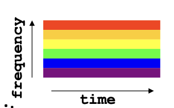
Packet Switching
Packet switching is where data is divided into packets that each contain a destination (dst) and is treated independently. Each packet can take their own route.
- There's no direct link between input port and output port. Its just a combination of ports and the packet destination will determine where it goes.
- Also known as "best effort" because you are not reserving/assumptions in the network, because you won't know what the performance level is.
Sending rate might be higher than the transmission rate, or everyone is sending to one destination. This may lead to transient overloads so we need to use buffers to absolve.
- buffers are not present in circuit switching.
Pros:
- efficient use of the network resource
- simpler to implement
- robust: can "route around the trouble"
- Network will never block senders
- low delay to send data
- high utilization under most workloads
- no per-connection network stake
Cons:
- unpredictable performance
- requires buffer management and congestion control.
Match the pro with the type:
- predictable performance | circuit because the resource allocation is agreed upon
- network never blocks sender | packet because in circuit, they could tell you no connection can be made
- reliable, in-order delivery | circuit
- low delay to send data | packet because you just send it without making the establishment
- simple forwarding | circuit because there's a direction connection already established. In packet switching you have to add a field for the destination.
- no overhead for packet headers | circuit because in packet switching you have to add a field for the destination.
- high utilization under most workloads | packet does have more network utilization because you need to direct it, but its better if its not consistent.
- no per-connection network state | packet because we don't save any states in the network.
Statistical multiplexing is a technique used to efficiently share network resources among multiple hosts. The available bandwidth is dynamically allocated based on the actual demand from different sources. Since users share the available bandwidth rather than having fixed resources, it is used so that you can demand more than the network may have been able to handle.
- just hope that not all demands are required at the same time
- results in unpredictability
- works well except for in extreme cases.
- unlike
IPv4 Address
The IP Address in IPv4 is a unique 32-bit number that identifies an interface (on host, on a router, ...) and is represented in dotted-quad notation.
- E.g.,
00001100 | 001000010 | 10011110 | 00000101is a address that has four sections of 8-bit numbers. In this example, the values represent the IP address12.34.158.5. 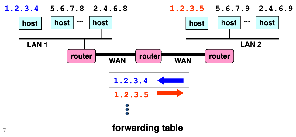
The internet is an "inter-network", meaning that there are small groups of hosts that are connected in a local area network, or LAN. Then, a router connects these LANs to all the other LANs. The whole internet is called wide area network, or WAN, and they connect all the LANs.
Hierarchical Addressing
Suppose hosts had arbitrary addresses, then every router would need a lot of information to know how to direct packets towards every host. This would be inefficient in memory because a for a packet in the WAN, the router would have to look at every single host address in each LAN to determine which router to send the packet to.
The solution is to use hierarchical addressing, which uses IP prefixes. The network and host portions are split up in the address on the left and right.
- E.g., the same example above,
00001100 | 001000010 | 10011110 | 00000101would have the first 24 bits be the 24-bit prefix or the network portion, and the last 8 bit the host portion. In this example, it would translate to 12.34.158.0/24 with addresses. Every host in the same subnet would share the same network address and differ in the host portion. - This improves scalability because all the related hosts (in a single LAN) would have a common subnet. By looking at the first portion of the bits, we know which router to send it to (no need to match the entire address)
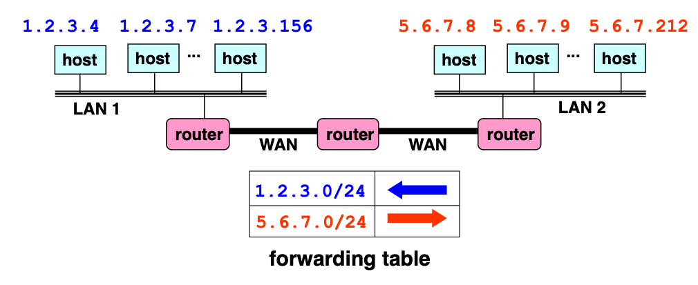
- Another benefit is that it's easy to add new hosts, because you do not need to update the routers. E.g., in the above example, if you wanted to add host
5.6.7.213on the right LAN, we don't need to add a new forwarding-table entry in the router.
A subnet mask would be used to calculate the network portion
00001100 | 001000010 | 10011110 | 00000101
11111111 | 111111111 | 11111111 | 00000000
CIDR
In the old days, there were a few classes of addressing. Each class had fixed allocation sizes. (this is why we use dotted-quad notations)
- Class A:
0*were very large/8blocks (e.g., MIT had18.0.0.0/8) (this means that the rest of the 24 bits could be dedicated to hosts) - Class B:
10*are large/16blocks - Class C:
110*are small/24blocks - Class D:
1110*was for multicast groups - Class E:
11110*was reserved for future use
They realized some of these blocks were too big. Then came classless inter-domain routing (CIDR). Use two 32-bit numbers to represent a number. One number is the IP Address and the other is the IP mask. Performing an AND operation gets you the network number.
- E.g., IP address =
00001100 | 00000100 | 000011010 | 00000000(12.4.10.0) and IP address =11111111 | 11111110 | 00000000 | 00000000(255.254.0.0) together is written as 12.4.0.0/15 - We use CIDR today.
Hierarchical address allocation is the key to scalability. Address allocated in contiguous chunks (prefixes). Today, the internet has around 400,000 prefixes.
- For example, one entity like JHU can have a
/8network and they can allocate to a/16network for the JHU CS department. Subnetworks can be made in this way. This way, if we wanted to direct something to the JHU CS department, it would first be sent to the JHU network, and then the JHU network forwards it to the CS department, then the lab itself.
IPv6
We exhausted IPv4 addresses. It uses 128 bits (4 times as big).
- Focused on simplifying IP, so they got rid of fields that were not absolutely necessary.
- Resulted in an elegant, unambitious protocol.
Backwards compatible- we use both IPv4 and IPv6 today. The differences are as follows:
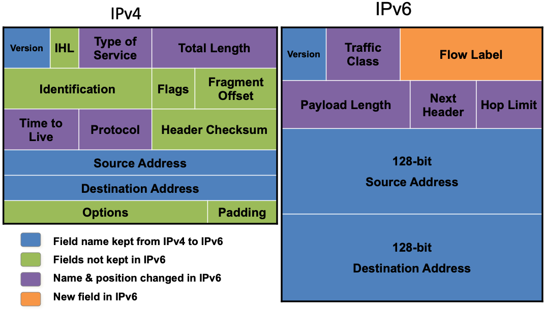
Philosophy of changes
- Removed IHL(header length) in order to process packets fast, we need to know the exact size of the header, so they made it fixed (40 bytes). This meant we could. Which was important in knowing how to parse the packet.
- removed fragmentation, because if we know the minimum MTU of the links, we don't need to fragment anymore. Leave that job to the end hosts (Transport layer should handle this)
- removed checksum because the end host is responsible for checking for corruption; don't check it every time in the network. This speeds up packet processing.
- kept type of service so we know priority. I.e., transport videos faster. Traffic classes are defined.
- payload length replaces total length in IPv4, but we only capture the length of the IP payload.
- kept TTL, which is now called hop count limit. End host has no information on what's happening in the network, so TTL must be kept to avoid any loops from occurring in the network.
- removed option and padding (now in next header)
- kept protocol (e.g., 6 is TCP) now in "next header". This also includes new options mechanism. If someone wanted to do fragmentation or something, they would add an extension header after the IPv6 header and define this in the "next header.
- added general "flow label" for packet. In data streaming, we sometimes want the packets in one connection to travel one particular route (instead of multiple) because we wanted to arrive in order so that the end hosts have an easier time. IPv6 doesn't define what the flow is, it just provides a field. It's something that provides flexibility for handling packets.
Linked from Computer Networks