Link Layer
Data Link
The datalink layer is present everywhere, and it transfers data between adjacent nodes or between nodes on the same local area network.
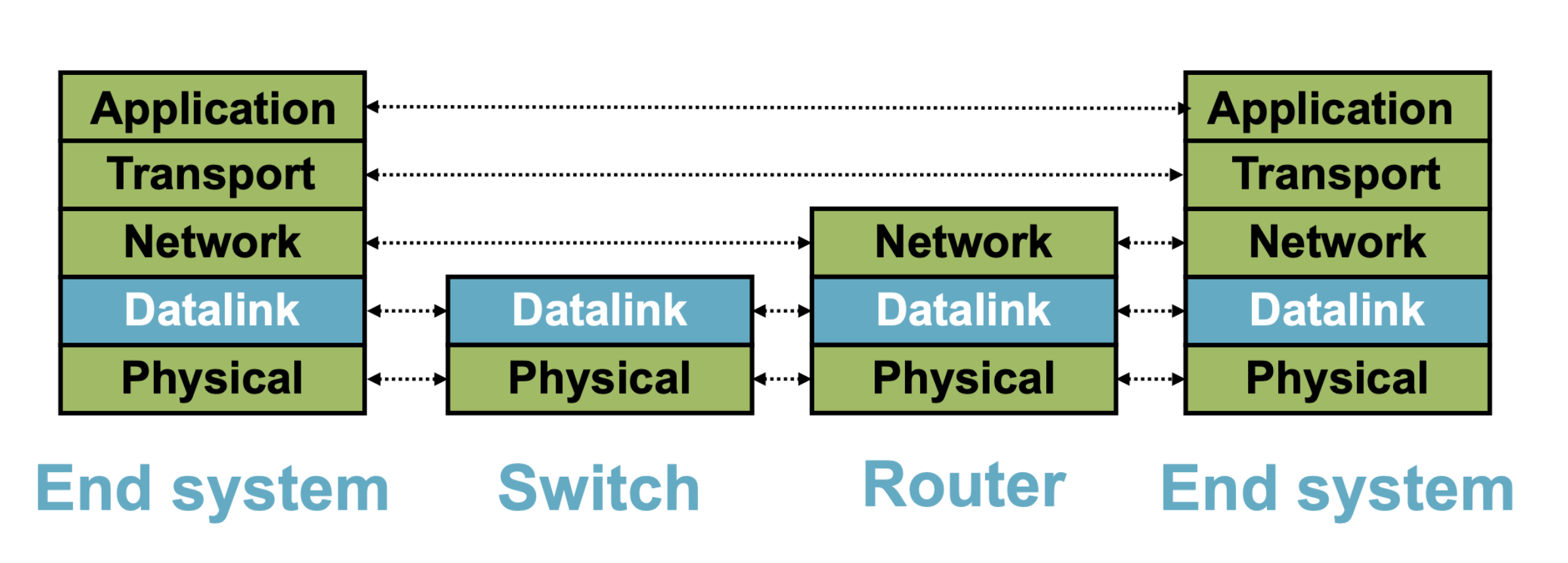
The data link layer provides four primary services:
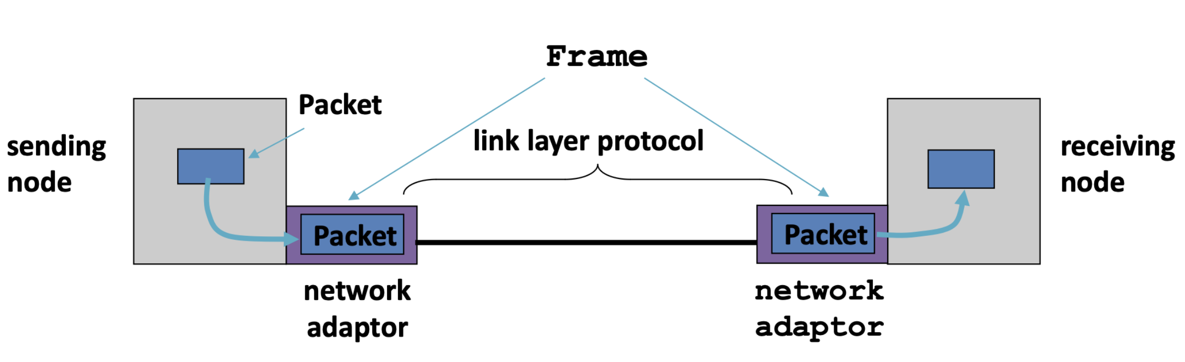
- frame: encapsulates network layer data
- link access: medium access control (MAC) protocol defines when to transmit frames.
- reliable delivery: primary for medium with high error rates (e.g., wireless)
- Error detection and correction
Packets are now called frames. Frames encapsulate network layer packets. Link layer protocols are implemented in hardware (in the chips like network adapters or network interface cards). Frame formats can change based on link layer protocol.
Point-to-point: dedicated pairwise communication.
- e.g., long-distance fiber link, point-to-point link between Ethernet switch and host.
Broadcast: shared wire or wireless medium
- E.g., traditional ethernet (pre ~2000), 802.11 wireless LAN, 4G/5G, satellite, shared radio (wifi), shared radio (satellite).
Multiple access algorithm
Context: a shared broadcast channel must avoid having multiple nodes speaking at once. Otherwise, collisions lead to garbled data. Need distributed algorithm to determine which node can transmit.
Three classes of techniques:
- channel partitioning: divide channel into pieces.
- If and only if the load is high can channel partitioning be considered fair and efficiency because if everyone has something to send, then we use the whole channel (not wasting the channel bandwidth).
- taking turns: scheme for deciding who transmits.
- have a single scheduler that asks everyone if they have anything to send. After gathering the responses, it schedules the transmission. This is called "polling".
- random access: allow collisions, and then recover (more in the Internet style).
Random Access
Random Access Protocols:
- when node has packet to send, it transmit at full channel data rate w/o coordination
- When two or more nodes are transmitting, then there is collision and data is loss.
- Random access protocol specifies how to detect and recover from collisions.
- E.g., ALOHA, and Slotted ALOHA for wired; CSMA, CSMA/CD, CSMA/CA (wireless)
Ethernet
Ethernet was invented as a broadcast technology
- hosts share channel
- each packet received by all attached hosts
- CSMA/CD for media access control
Modern ethernets are "switched"
- point-to-point links between switches and between a host and switch
- no sharing -> no CSMA/CD
- uses "self learning" and "forwarding and filtering algorithms for routing"
Carrier Sense Multiple Access
Carrier Sense Multiple Access (CSMA): listen before transmit. If channel sense is idle; transmit entire frame. If channel sensed busy, defer transmission.
- Human analogy: don't interrupt others
- CSMA will reduce but not eliminate all collisions because of propagation delay, meaning that the nodes may not hear each other before sending.
- If a collision occurs, entire packet transmission time is wasted. Distance and propagation delay affect collision probability.
CSMA/CD (Collision Detection): carrier sensing, deferral as in CSMA. Collisions detected within short time. Colliding transmissions aborted, reducing wastage. ^lsb7p6
- collision detection is easy in wired (broadcast) LAN. You can compare transmitted and received signals. If
- Collision detection is difficult in wireless LAN.
Key ideas of random access:
- Carrier sense: listen before speaking and don't interrupt. Check is someone else is already sending data, and wait until the other node is done.
- Collision detection: if someone else starts talking at the same time, stop and make sure everyone knows there was a collision. Realize when two nodes are transmitting at once by detecting that the data on the wire is garbled.
- Randomness: don't start talking again right away. Wait for a random time before trying again.
Ethernet uses CSMA/CD Protocol:
- carrier sense: wait for the link to be idle
- collision detection: listen while transmitting. No collision means that transmission is complete. Collision means abort transmission and send jam signal.
- random access: binary exponential back-off.
- After collision, wait a random time before retrying
- After collision, choose randomly from .
- Waits for bit times before trying again. If transmission occurring when ready to send, wait until end of transmission (CSMA). If you experience more transmission, this means that more nodes are sending at the same time. So with this method, you try to guess the number of node that is sending stuff at the same time.
Switched Ethernet
Previously, we talked about traditional ethernet. Now, it's implemented with switches.
Broadcast vs switched ethernet.
- Traditionally, it was invented as a broadcast technology. Hosts would share a channel, each packet received by all attached hosts. CSMA/CD for media access control.
- Modern ethernets are "switched".
- Point-to-point links between switches and between a host and switch.
- No sharing -> no CSMA/CD. It uses "self learning" and "filtering and forwarding" algorithm for routing.
Why use switched ethernet? It enables concurrent communication. There's no collision when host A talks to C while B talks to D. This means there's no need for CSMA/CD. There is no constraint on link lengths, etc.
- made by Bob Metcalfe (ethernet co-inventor, 2022 ACM Turing Award Recipient).
- Backwards compatible, simple, beautiful.
Ethernet Frames
An ethernet frames encapsulates an IP datagram and some other things:
- preamble: 7 bytes for clock synchronization and 1 byte to indicate start of frame
- address: 6 bytes
- type: 2 bytes, higher-layer protocol (e.g., IP)
- data payload: max 1500 bytes, min 46 bytes
- CRC: 4 bytes for error detection
How does the framing work? Physical layer puts bits on a link. But, two hosts connected on the same physical medium need to be able to exchange frames.
- service provided by the link layer
- implemented by the network adaptor.
The framing problem is how does the link layer determine where each frame begins and ends?
Count Bytes
Count bytes is the simple approach.
- The sender includes number of bytes in the header. The receiver will extract this number of bytes of body.
- What if the count field is corrupted? The L2 will frame the wrong bytes, causing a framing error. CRC will tell you to discard this frame, but what about the next one? This is called desynchronization
Sentinel Bit Stuffing
Once framing on a link is desynchronized, then it will stay that way. You need a method to resynchronize. This is where the strategy of framing with sentinel bits. Delineate frame with special "sentinel" bit pattern. E.g., 01111110 is the start and 01111111 is the end.
What if sentinel occurs within frame? The solution is bit stuffing:
- sender always inserts a 0 after five 1s in the frame contents.
- receiver always removes a 0 appearing after five 1s.
When receiver sees five 1s:
- if next bit is
0, remove it; begin counting again. This is because this must be a stuffed bit, we can't be at the beginning/end of frame (those had six or seven1s) - if the next bit is
1(i.e., we've seen six1s) then:- if following bit is
0, this is the start of frame because the receiver has seen01111110 - if the following bit is
1this is the end of the frame, because the receiver has seen01111111
- if following bit is
This works because after bit stuffing, it is impossible for the data to have 6 1's in a row.
Example of sentinel bits:
- Original data including the start and end of the frame:
01111110011111101111101111100101111111 - Sender rules: if you see five
1s, the insert a0. After bit stuffing at the sender:01111110011111010111110011111000101111111 - Receiver rule: five
1s and next bit0-> remove the0:01111110011111101111101111100101111111
Addressing
Medium Access Control (MAC) Address. These are numerical addresses associated with a network adapter. It has a flat name space of 48 bits (e.g., 00-15-C5-49-04-A9). Unique, hard-coded in adapter when it is built.
Hierarchical allocation:
- blocks: assigned to vendors (e.g., Dell) by the IEEE. First 24 bits (e.g.,
00-15-C5-**-**-**) - adapter: assigned by the vendor from its block (last 24 bits).
MAC vs IP address:
- Mac addresses are hard-coded when adapter is built. There is a flat namespace of 48 bits. Similar to a social security number. Its portable, and can stay the same as the host moves. Its used to get between interfaces on the same network.
- IP addresses are configured, or learned dynamically. It has has a hierarchical namespace of 32 bits. It's like a postal mailing address. Not portable, and depends on where the host is attached. Used to get a packet to destination IP subnet.
Forwarding
An ethernet switch is a link-layer device that takes an active role
- store, forward Ethernet (or other type of) frames.
- examine incoming frame's MAC address, selectively forward frame to one-or-more outgoing links.
They are transparent, meaning that hosts are unaware of presence of switches
Plug-and-play or self-learning, meaning that switches do not need to be configured.
Switching
A switch can have multiple simultaneous transmissions.
- Hosts have dedicated, direct connection to switch.
- Switches buffer packets.
- The ethernet protocol is used on each incoming link, so there is no collisions; fully duplex; and each link is its own collision domain.
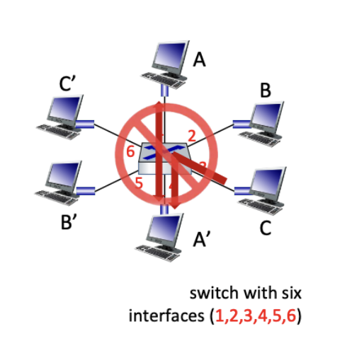
Switching: A-A' and B-B' can transmit simultaneously, without collision. However, A-A' and C-A' cannot happen simultaneously.
So how does switch know that A' is reachable via interface 4, B' is reachable via interface 5?
- each switch has a switch table, where each entry has the (MAC address of the host, interface to reach host, time stamp). It looks like a routing table
How are entries created and maintained in a switch table? Self learning switches learn which host can be reached through which interfaces when the frame is received. When a frame received, then the switch will "learn" the location of the sender: the incoming LAN segment. It records this sender/location pair in the switch table. The switch table is initially empty.
A miss example: say frame destination A' is unknown. Then you flood the frame to very single port except for the port you received the frame (in this example, A). Each receiver will check if its intended for it, and if it is, then it responds to the switch by sending it to A. We know the destination A' location is known, so it'll selectively send on just one link.
Self learning
Ethernet switches are "self learning". When a packet arrives:
- inspect source MAC address, associated with an incoming port
- store mapping in the switch table
- use time-to-live field to eventually forget mapping.
Essentially, the packet tells the switch how to reach A.
Handling misses:
- when packet arrives with unfamiliar destination
- we forward packet out to other ports
- response may teach switch about that destination.
In summary of learning approach:
- We approach a loop by restricting to spanning tree
- This makes flooding possible.
- Flooding allows packet to reach destination
- And in the process switches learn how to reach the source of the flood.
- Important for the assignment!
- No route "computation." We just send the packet and use this information to fill the forwarding table
- Forwarding entries distinction- Its a consequences of traffic pattern.
The big advantage of ethernet switches is that its plug and play. You only plug it into the host and you don't need a computation algorithm. When traffic is sent over the network, the switch will eventually learn about the host. Simple implementation. The big disadvantage is that its slow to predict changes in the network. If you move the host to a different LAN, it takes the whole TTL time to remove it from the forwarding table.
Discovery
Discovery is the last layer of the network, so we need to find the way to communicate with others, which requires information about yourself and others. How do we know we can communicate on the link layer?
A host is "born" knowing only its MAC address (done at manufacturing). To communicate to other nodes like node B (inside or outside your LAN), you need to know:
- my IP address
B's IP address (ifBis remote)B's MAC address (ifBis local)- What is the first-hop router's address (if
Bis not local)
To figure out this information, there are two discovery protocols in the link layer:
- ARP, or Address Resolution Protocol, is responsible to discover local end-hosts for communication between hosts on the same LAN.
- DHCP, or Dynamic Host Configuration Protocol, is responsible for bootstrap communication with remote hosts. Its used to figure out your own IP address, your local DNS server, your first hop (who/what).
- The are confined to a single local-area network (LAN).
- They both rely on broadcast capabilities.
Dynamic Host Configuration Protocol
Dynamic Host Configuration Protocol is defined in RFC 2141. A host will use DHCP to discover
- its own IP address
- its netmask (what range can it support?)
- IP address(es) for its local DNS name server
- IP address(es) for its first-hop "default" router(s)
DHCP operation: In any LAN, you can have one or more local DHCP servers maintain the required information above. Its an application that listens on UDP port 67.
- As an example, there is a pool of IP addresses in these subnet masks. This is the list of IP addresses that hasn't been taken.
The client broadcasts a DHCP discovery message: a L2 broadcast to MAC address FF:FF:FF:FF:FF:FF
One or more DHCP servers responds with a DHCP "offer" message. It proposes an IP address for the client, the lease time, and other parameters.
The client broadcasts a DHCP request message, which specifies which offer it wants and echos the accepted parameters. The other DHCP servers will learn that they were not chosen.
The selected DHCP server responds with an ACK.
==what exactly does each DHCP maintain, what is chosen==
DHCP uses a "soft state": if its not refreshed, the state is forgotten. On the other had, hard state: is when the allocation/revocation is deliberate. This is when you have the lease.
The implementation
- Each address allocation has a lease period
- Server sets a timer for each allocation
- Client must request a refresh before the lease expires
- Server would then reset the timer when a refresh arrives and ACKs, or it reclaims allocated address when timer expires.
Soft state was created so that we could have a simple robust system to deal with failure.
- This is necessary so that when a device disconnects (without sending a close), the network will not keep their addresses valid, so that it can reuse.
E.g., address a.b.c.d is host XYZ's. What would happen when host XYZ fails?
- the refreshes from XYZ would stop coming
- so then the server would reclaim
a.b.c.dafter O(lease period).
Now, what would happen when the servers fail?
- the ACKs from the server stop
- XYZ releases address after O(lease period) and it sends new request
- A new DHCP server can come from a 'cold start' and we are back on track in ~lease time.
What would happen if the network fails?
- refreshes and ACK's cant get through
- XYZ releases address; DHCP server reclaims it
To send packets over the link layer, we still need MAC addresses, because its needed for the headers of the frames (srchw and dsthw). It needs to be able to translate the destination IP address with the MAC address and encapsulate the IP packet in the link-level (Ethernet) frame.
Recap: we start with sending a HTTP request to get a HTTP response. We have IP addresses for each of the web server, in order to communicate with other services. We ask the DNS for this IP address. This is why we need a DNS in our network, in order to translate to IP address .
Address Resolution Protocol
Address Resolution Protocol: every host maintains an ARP table, which is a list of IP address -> MAC address pairs. We consult with this table when sending a packet. We will encapsulate the IP data packet with MAC header before we transmit.
What if IP address is not in the table?
- The sender broadcasts: who has IP address
1.2.3.156 - Receiver would reply: MAC address
57-23-d7-fa-20-f0 - sender caches this result in its arp table.
What if the destination is remote? (like the IP address is somewhere not in your LAN, like accessing google)
- Look up the MAC address of the first hop router (instead of the MAC of the Google server)
1.2.3.48uses ARP to find MAC address for first-hop router1.2.3.19(which has access to routers outside your LAN) rather than ultimate destination IP address
How does the host know that the destination is not local?
- it uses netmask (discovered via DHCP)
How does the host know about the IP address of the first hop?
- Also from the DHCP
ARP vs DHCP
In both ARP and DHCP there are a few key ideas:
- broadcasting: we use broadcasting to make contact. This only works in this situation because of its limited size
- caching: remember the past for a while. We store the information so that we don't need to reconfigure and that way we can reduce overhead.
Discovery mechanisms:
- broadcast (ARP, DHCP)
- flooding / does not scale
- no central point of failure
- zero configuration
- directory service (DNS)
- no flooding / is more scalable (necessary because the scale is the whole internet)
- root of the directory is vulnerable (we have 13 DNS roots) / caching is key
- needs configuration to bootstrap (before we can start using it) (local, root servers, etc.)
Overview: ID resolution in the networking stack:
| layer | ex | structure | configuration | resolution service |
|---|---|---|---|---|
| app | cs.jhu.edu | organizational hierarchy | ~manual | dns v |
| network | 123.45.6.7.8 | topological hierarchy | DHCP | dns ^ arp v |
| link | 45-cc-4e-12-d0-87 | vendor(flat) | hard-coded | arp ^ |
Virtual LANs
What happens when LAN sizes get big, and users change their point of attachment:
Single broadcast domain:
- scaling: all layer-2 broadcast traffic (ARP, DHCP, unknown MAC) must cross entire LAN
- efficiency, security, privacy, issues.
- we might want the information to be contained in certain groups
administrative issues:
- CS user moves office to EE-physically attached to EE switch, but wants to remain logically attached to CS switch.
A Virtual Local Area Network (VLAN) there are switch(es) supporting VLAN capabilities can be configured to define multiple virtual LANs over single physical LAN infrastructure.
Port-based VLAN: switch ports grouped (by switch management software) so that there is a single physical switch and it operates as multiple virtual switches.
- traffic isolations. E.g., frames to/from 1-8 can only reach ports 1-8. You can also define VLAN based on MAC addresses of endpoints, rather than by switch port
- dynamic membership: ports can be dynamically assigned among VLAN
- forwarding between VLAN is done via routing (just as with separate switches). In practice, vendors sell combined switches plus routers.
VLANS can span multiple switches.
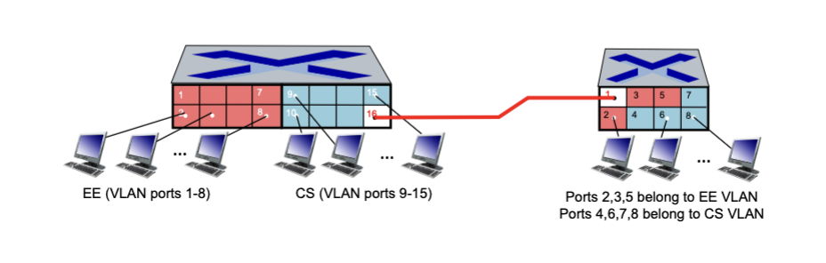 The trunk port carries frames between VLANs defined over multiple physical switches.
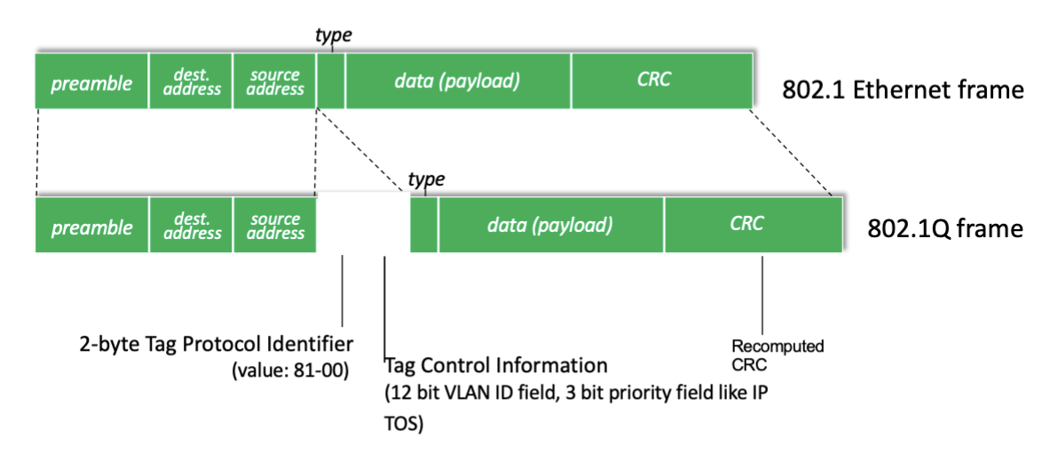
- frames forwarded within VLAN between switches can't be vanilla 802.1 frames because it must carry VLAN IDs.
- 802.1q protocol adds/removed additional header fields for frames forwarded between trunk ports.
The 802.1q VLAN frame format:
Linked from Computer Networks, Wireless Networks